On Electric Machines Founded on Induction and Convection
By Sir William Thomson (Lord Kelvin)
Philosophical Magazine, January 1868
416. To facilitate the application of an instrument, which I have recently patented, for recording the signals of the Atlantic Cable, a small electric machine running easily enough to be driven by the wheelwork of an ordinary Morse instrument was desired; and I have therefore designed a combination of the electrophorus principle with the system of reciprocal induction explained in [§§ 401...407] a recent communication to the Royal Society (Proceedings, June 1867), which may be briefly described as follows:—
417. A wheel of vulcanite, with a large number of pieces of metal (called carriers, for brevity) attached to its rim, is kept rotating rapidly round a fixed axis. The carriers are very lightly touched at opposite ends of a diameter by two fixed tangent springs. One of these springs (the earth-spring) is connected with the earth, and the other (the receiver-spring) with an insulated piece of metal called the receiver, which is analogous to the “prime conductor” of an ordinary electric machine. The point of contact of the earth spring with the carriers is exposed to the influence of an electrified body (generally an insulated piece of metal) called the inductor. When this is negatively electrified, each carrier comes away from contact with the earth-spring, carrying positive electricity, which it gives up, through the receiver-spring, to the receiver. The receiver and inductor are each hollowed out to a proper shape, and are properly placed to surround, each as nearly as may be, the point of contact of the corresponding spring.
418. The inductor, for the good working of the machine, should be kept electrified to a constant potential. This is effected by an adjunct called the replenisher, which may be applied to the main wheel, but which, for a large instrument, ought to be worked by a much smaller carrier-wheel, attached either to the same or to another turning-shaft.
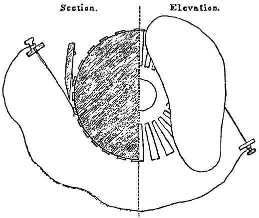
Fig. 1.
419. The replenisher consists chiefly of two properly shaped pieces of metal called inductors, which are fixed in the neighbourhood of a carrier-wheel, such as that described above, and four fixed springs touching the carriers at the ends of two diameters. Two of these springs (called receiver-springs) are connected respectively with the inductors; and the other two (called connecting springs) are insulated and connected with one another (one of the inductors is generally connected with the earth, and the other insulated.) They are so situated that they are touched by the carriers on emerging from the inductors, and shortly after the contacts with the receiver-springs. If any difference of potential between the inductors is given to begin with, the action of the carriers, as is easily seen, increases it according to the compound-interest law as long as the insulation is perfect. Practically, in a few seconds after the machine is started running, bright flashes and sparks begin to fly about in various parts of the apparatus, even although the inductors and connectors have been kept for days as carefully discharged as possible. Forty elements of a dry pile (zinc, copper, paper), applied with one pole to one of the inductors, and the other for a moment to the connecting springs and the other inductor, may be used to determine, or to suddenly reverse, the character (vitreous or resinous) of the electrification of the insulated inductor. The only instrument yet made is a very small one (with carrier-wheel 2 inches in diameter), constructed for the Atlantic Telegraph application; but its action has been so startlingly successful that good effect may be expected from larger machines on the same plan.
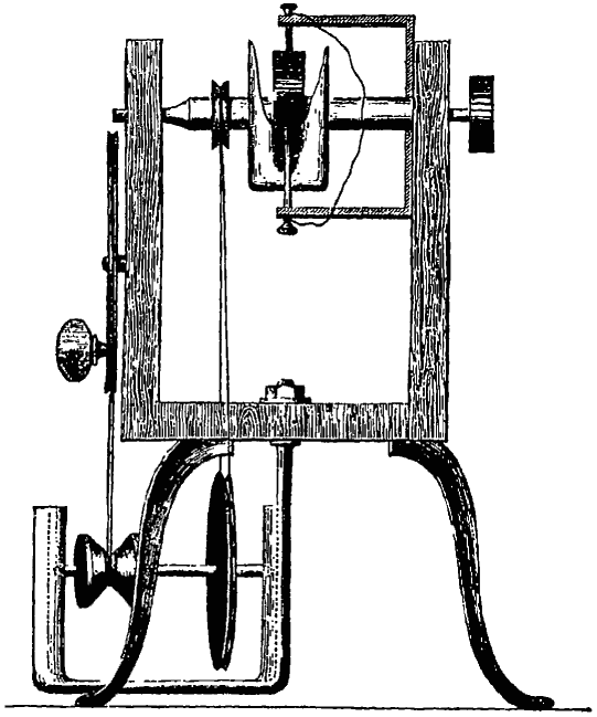
Fig. 2.
420. When this instrument is used to replenish the charge of the inductor in the constant electric machine, described above, one of its own inductors is connected with the earth, and the other with the inductor to be replenished. When accurate constancy is desired, a gauge-electroscope is applied to break and make contact between the connector-springs of the replenisher when the potential to be maintained rises above of falls below a certain limit.
421. Several useful applications of the replenisher for scientific observation were shown by the author at the recent meeting of the British Association (Dundee),—among others, to keep up the charge in the Leyden jar for the divided-ring mirror-electrometer, especially when this instrument is used for recording atmospheric electricity. A small replenisher, attached to the instrument within the jar, is worked by a little milled head on the outside, a few turns of which will suffice to replenish the loss of twenty-four hours.
Postscript, Nov. 23, 1867.
422. As has been stated, this machine was planned originally for recording the signals of the Atlantic Cable. The small “replenisher” represented in the diagrams has proved perfectly suitable for this purpose. The first experiments on the method for recording signals which I recently patented were made more than a year ago by aid of an ordinary plate-glass machine worked by hand. This day the small “replenisher” has been connected with the wheelwork drawing the Morse paper on which signals are recorded, and, with only the ordinary driving-weight as moving power, has proved quite successful.

Fig. 3.
423. The scientific applications indicated when the communication was made to the British Association have been tested within the last few weeks, and especially to-day, with the assistance of Professor Tait. The small replenisher is now made as part of each quadrant electrometer. It is permanently placed in the interior of the glass Leyden jar; and a few turns by the finger applied to a milled head on the outside of the lid are found sufficient to replenish the loss of twenty-four hours. A small instrument has also been made and tested for putting in practice the plan of equalizing potentials, described verbally in the communication to the British Association, which consisted in a mechanical arrangement to produce effects of the same character as those of the water-dropping system, described several years ago at the Royal Institutaion. [1] The instrument is represented in the annexed sketch (fig. 3). AT and A′T′ are two springs touching a circular row of small brass pegs [2] insulated from one another in a vulcanite disc. These springs are insulated, one or both, and are connected with the two electrodes of the electrometer—or one of them with the insulated part of the electrometer, and the other with the metal enclosing the case, when there is only one insulated electrode. One application is to test the “pyro-electricity” of crystals; thus a crystal of tourmaline, PN, by means of a metal arm holding its middle, is supported symmetrically with reference to the disc in a position parallel to the line TT′, and joining the lines of contact of the springs. When warmed (as is conveniently done by a metal plate at a considerable distance from it), it gives by ordinary tests, as is well known, indications of positive electrification towards the one end P, and of negative electrification towards the other end N. The wheel in the arrangement now described is kept turning at a rapid rate; and the effect of the carrier is to produce in the springs TA, T′A′ the same potentials, approximately, as those which would exist in the air at the points T, T′ if the wheel and springs were removed. The springs being connected with the electrodes of the divided-ring quadrant electrometer, the spot of light is deflected to the right, let us say, After continuing the application of heat for some time the hot plate is removed, and a little later the spot of light goes to zero and passes to the left, remaining there for a long time, and indicating a difference of potentials between the springs, in the direction A′T′ positive and AT negative. The electrometer being of such sensibility as to give a deflection of about 100 scale-divisions to the right or left when tested by a single galvanic cell, and having a range of 300 scale-divisions on each side, it is necessary to place the tourmaline at a distance of several inches from the disc to keep the amount of the deflection within the limits of the scale.
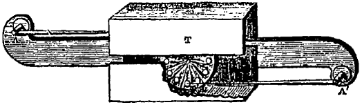
Fig. 4.
424. Another application of this instrument is for the experimental investigation of the voltaic theory, according to the general principle described [§ 406] in the communication to the Royal Society already referred to. [3] In it two inductors are placed as represented in fig. 4. The inner surface of each of these is of smooth brass; and one of them is lined wholly, or partially, with sheet zinc, copper, silver, or other metal to be tested. Thus, to experiment upon the contact difference of potentials between zinc and copper, one if the inductors is wholly lined with sheet zinc or with sheet copper, and the two inductors are placed in metallic communication with one another. The springs are each in metallic communication with the electrodes of the quadrant mirror electrometer, and the wheel is kept turning. The spot of light is observed to take positions differing, according as the lining is zinc or copper, by 72½ per cent. of the difference produced by disconnecting the two inductors from one another and connecting them with the two plates of a single Daniell’s cell, when either the zinc or the copper lining is left in one of them. These differences are very approximately in simple proportion to the differences of potentials between the pairs of the opposite quadrants of the electrometer in the different cases. The difference between the effects of zinc and of copper in this arrangement is of course in the direction corresponding to the positive electrification of the quadrants connected with the spring whose point of contact is exposed to the zinc-lined inducing surface. It must be remembered, however, as is to be expected from Hankel’s observations, that the difference measured will be much affected by a slight degree of tarnishing by oxidation, or otherwise, of the inner surface of either inductor. When the copper surface is brought to a slate-colour by oxidation under the influence of heat, the contact difference between it and polished zinc amounts sometimes, as I found in experiments made seven years ago, to 125, that of a single cell of Daniell’s being called 100.
425. A useful application of the little instrument represented in fig. 4 is for testing insulation of insulated conductors of small capacity, as for instance, short lengths (2 or 3 feet) of submarine cable, when the electrometer used is such that its direct application to the conductor to be tested would produce a sensible disturbance in its charge, whether through the capacity of the electrometer being too great, or from inductive effects due to motion of the moveable part, or parts, especially if the electrometer is “heterostatic” [§ 385]. In this application one of the inductors is kept in connexion with a metal plate in the water surrounding the specimen of cable to be tested; and the other is connected with the specimen, or is successively connected with the different specimens under examination. The springs are connected with the two electrodes of the electrometer as usual. The small constant capacity of the insulated inductor, and the practically perfect insulation which may with ease be secured for the single glass of vulcanite stem bearing it, are such that the application of the testing apparatus to the body to be tested produces either no sensible change, or a small change which can be easily allowed for. It will be seen that the small metal pegs carried away by the turning-wheel from the point of the insulated spring, in the arrangement last described, correspond precisely to the drops of water breaking away from the nozzle in the water-dropping collector for atmospheric electricity.
426. A form bearing the same relation to that represented in the drawings that a glass-cylinder electric machine bears to a plate-glass machine of the ordinary kind will be more easily made, and will probably be found preferable, when the dimensions are not so great as to render it cumbrous. In it, it is proposed to make the carrier-wheel nearly after the pattern of a mouse-mill, with discs of vulcanite instead of wood for its ends. The inductor and receiver of the rotatory electrophorus or the two inductor-receivers of the replenisher, may, when this pattern is adopted, be mere tangent planes; but it will probably be found better to bend them somewhat to a curved cylindrical shape not differing very much from tangent planes. When, however, great intensity is desired, the best pattern will probably be had by substituting for the carrier-wheel an endless rope ladder, as it were, with cross bars of metal and longitudinal cords of silk or other flexible insulating material. This, by an action analogous to that of the chain-pump, will be made to move with great rapidity, carrying electricity from a properly placed inductor to a properly shaped and properly placed receiver at a distance from the inductor which may be as much as several feet.
Footnotes
-
[1] Lecture on Atmospheric Electricity, Proceedings of the Royal Institution, May 1860. See also Nichol’s Cyclopædia, article “Electricity, Atmospheric” [§§ 249...293].
-
[2] [I now find a smaller number of larger discs to be preferable, as considerable disturbances are produced by the numerous breakings of contact unless the two springs are in precisely the same condition as to quality and cleanness of metal surface. Thin stiff platinum pins attached to the discs, and very fine platinum springs touching them as the pass, will probably give good and steady results if the springs are kept very clean. The smallest quantity of the paraffin (with which, as usual in electric instruments, the vulcanite is coated), if getting on either spring, would probably produce immense disturbance.—December 23, 1867.]
-
[3] Proceedings of the Royal Society, May 1867.